Explainer: Refinery Skylines – Heater Stacks, Cooling Towers and More
Business News
Business, Environment, Safety
This article is part of Marathon's Explainer Series, which provides background information and facts about the company's operations and role in the energy industry.
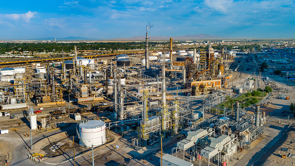
The towering structures of a refinery make a unique skyline recognizable from a distance. There are four structures that can be quickly identified once you know what to look for, and their functions are important parts of the safe and environmentally sound performance of the refinery. This explainer provides insight into the function of these essential structures and the processes behind the steam, exhaust gas or flares that are sometimes visible.
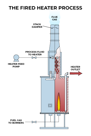
Stacks for Heaters or Boilers
- Purpose: Safely vent exhaust gas associated with energy used in the refining process (similar to a furnace or water heater in your home)
- Visual: Occasional water vapor when temperatures are cooler than the exhaust
- Source: Fuel burned in heaters and boilers
Heaters and boilers are among the most common pieces of equipment that can be found in a refinery. They boil crude oil and make refined products like gasoline and diesel. These processes occur at high temperatures. By combusting natural gas or refinery fuel gas, heat is generated and transferred to the material being processed. Waste gases, primarily carbon dioxide, water vapor, and other emissions, like small amounts of sulfur dioxide, oxides of nitrogen, carbon monoxide, volatile organic compounds, and particulate matter, are vented out of the heater stack, similar to how waste gases from a furnace in a home are safely vented outside the house. Boilers are used to create steam, which has various purposes in the refining process, including as a reactant or a way to transfer heat.

Stacks for FCC Flue Gas from Wet Gas Scrubbers
- Purpose: Safe emissions control
- Visual: Steam and exhaust gas
- Source: Product from the fluid catalytic cracker burned in a regenerator
Fluidized catalytic crackers, or FCCs, are one of the most economically prevalent pieces of equipment in a refinery. FCCs take low-value, gas oil (a fraction of hydrocarbons derived from distillation of petroleum with boiling points between diesel and resid) and convert it to higher-value gasoline components. The FCC utilizes a mix of conditions (temperature, pressure, catalyst) to cause larger molecules to “crack” into smaller but higher-value gasoline-range molecules. During this process, the catalyst will become “coked” (covered with carbon residue). This coked catalyst is sent to a regenerator, where high temperature combusts the coke so the catalyst can be used again. This process generates waste exhaust gas with emissions, sometimes called flue gas. Before the flue gases are released into the atmosphere, wet gas scrubbers or other emission control devices clean the exhaust. It is the water from the wet gas scrubbers that create the vapor you see emitting from the stack.

Cooling Towers
- Purpose: Heat removal
- Visual: Vapor
- Source: Heat exchangers
Many refining processes occur at high temperatures. The cooling water system uses heat exchangers to lower the temperature of these process streams by transferring the heat from the process stream to the water. The hot water is sent to a cooling tower where it is exposed to air and allowed to cool. Some of the water evaporates during this cooling process and the remainder falls to a reservoir at the bottom of the tower where it can then be recirculated back into the refinery to cool process fluids once again.


Flares
- Purpose: Primarily a safety device, also used for emissions control
- Visual: Flame
- Source: Various refinery equipment
Flares are first and foremost safety devices to help ensure equipment does not exceed designed pressure limits, but they also play an important role in emissions control. Most process units in a refinery are connected to the flare system. If a process unit experiences a high-pressure event, pressure relief valves will open and discharge material to the flare to lower the pressure in the process unit. The flare prevents releasing these flammable gases directly into the atmosphere by combusting them at the flare tip. Many flares also have steam or air injected at the tip to provide cooling and help provide optimum combustion conditions to reduce smoke and enhance combustion.


Monitoring
Refinery stacks are regularly monitored to support safe and compliant operations. Refinery employees use advanced analyzers like continuous emissions monitoring systems (CEMS) to track pollutants such as sulfur dioxide, nitrogen oxides, and carbon monoxide in real time. These systems provide data that can be used to measure performance and also demonstrate compliance with environmental permit limits. Stacks can also be assessed for visible emissions by using remote sensing tools and visual inspections to ensure that they meet environmental standards.
MPC is an industry leader in reducing flare emissions. Our flare reduction strategy focuses on source reduction (preventing gases from entering the flare system), waste gas recovery and optimizing flare combustion efficiency. The majority of our refineries have flare gas recovery systems that recover gas entering the flare system, so it can be used as fuel within the refinery instead of being burned by the flare. Recovering the gases reduces reliance on purchased natural gas, lowering overall greenhouse gas emissions.
For the gases that cannot be captured, MPC established operating parameters to optimally combust the materials that are sent to the flare. MPC was the first company to produce and publish the results of performance tests on our flares. Environment and Climate Strategy Senior Director Ruth Cade played a major role in implementing these standards and encouraging industry adoption.